The Perl Powered Christmas Tree
So, you want to run some Christmas tree lights. Not just any lights, but flashy blinky ones. And while you're at it, give them some nice pretty patterns using a few separate chains of lamps. Maybe Perl can help run those patterns?
The Software
It's simple enough of course to define some blinky patterns, perhaps by naming the light chains A to D, and using a sequence of strings to define the patterns of which ones should be on or off:
my @patterns = qw(
   AB CD AB CD AB CD AC BD AC BD AC BD BC AD BC AD BC AD ...
);
We could then use this string of patterns to drive the lights in some manner. For example, we could do something simple:
use Time::HiRes 'sleep';

while(1) {
   foreach my $pattern ( @patterns ) {
      set_lights( $pattern );
      sleep 0.5;
   }
}
Here we've got a nice simple repeating pattern that just runs all day long. But how might we implement this set_lights() function? We'll have to actually communicate with the outside world somehow; some actual piece of hardware.
Two specific pieces of hardware that could be useful here are the FTDI FT232H (most conveniently on a breakout board, such as the one made by Adafruit) and the Bus Pirate Made by Dangerous Prototypes, available from several places
These two devices are somewhat different in many respects, but both of them may be described as a USB-attached board which has several digital logic IO pins on board. They each support a mode of operation whereby several pins on the board (16 in the FTDI's case, 5 in the Bus Pirate) can be controlled directly by the computer, setting them directly high or low as required by the program. In our case we only need 4 for the light patterns described above so either would be sufficient for our purposes.
The Device::Chip module on CPAN describes an abstraction layer around various mechanisms that might be employed to talk to real hardware. It's still in its early phases yet so it doesn't have too many actual implementations, but it does support these two hardware boards. It exposes in each case an interface called a GPIO adapter (a "General Purpose Input/Output" - the most basic form of digital IO pin control), which allows us to directly control the high or low state of these pins.
Using this module we can obtain a object that represents the GPIO ability of the hardware and use the write_gpios() method on it to set the state of each GPIO pin. As a little technicality, because the Device::Chip distribution uses Future to make it possible to use asynchronously we'll just have to call the get() method on the Future returned by write_gpios() to actually force it to run. We'll also have to make sure to use names of the GPIO pins that the particular device will recognise.
# Convert names of our strings of lights to GPIO pin names on
# the adapter
my %CHAIN_TO_GPIO = (
   # If we're using the FT232H
   A => "D0", B => "D1", C => "D2", D => "D3",

   # If we're using the Bus Pirate
   A => "MISO", B => "CS", C => "MOSI", D => "CLK",
);

sub set_lights
{
   my ( $pattern ) = @_;

   # $pattern says what light chains to turn on; we'll also
   # have to turn the others off

   my %want_chains = map { $_ => 0 } qw( A B C D );
   $want_chains{$_} = 1 for split //, $pattern;

   # Now convert to the pin names required by Device::Chip
   my %gpios = map { $CHAIN_TO_GPIO{$_} => $want_chains{$_} }
               keys %want_chains;

   $gpio->write_gpios( \%gpios )->get;
}
All we need now to make our program complete is to initialise this $gpio object at the beginning by opening the actual hardware object. This too comes from Device::Chip using the handy utility constructor on the Device::Chip::Adapter class called new_from_description() to first obtain an object representing the hardware adapter itself, and then calling its make_protocol() method to switch it into GPIO mode and obtain an object specifically representing that.
use Device::Chip::Adapter;

my $adapter = Device::Chip::Adapter->new_from_description(
   "FTDI",  # Or BusPirate, or whatever...
);

my $gpio = $adapter->make_protocol( "GPIO" )->get;
The Hardware
Now we've got a method of controlling these digital IO lines from perl we can now consider how to actually attach to the actual light chains to it. These IO lines are only capable of controlling 3.3V or 5V up to about 20mA or so; nowhere near enough for some lights. "Low voltage" lights are likely 12 or 24V, and mains ones will run at either 230V or 110V, depending on local supply.
To do this we'll need some kind of adapting interface between the digital IO line and the light chain. For a low voltage chain of moderate current (such as a string of LEDs) we can probably use a single NPN transistor along with current-limiting resistor on the base:
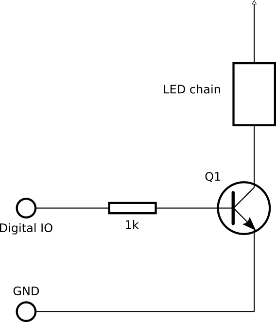
When the digital IO line is high it drives a current through the transistor (Q1) to ground which allows the transistor to conduct a larger current through the lamp chain, making it light up. When the line is low the base current stops and so the lamp chain goes off.
There's a limit to how much current we can switch using this arrangement though - any transistor acts much like a current multiplier; allowing a collector-emitter current to flow that is some multiple of the base-emitter current (usually of the order of 50 times as much). Because the digital IO line on our controller is probably only capable of 20mA or so, that limits our ability to switch lamps up to about 1A.
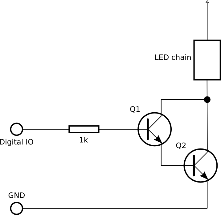
To achieve a higher current (perhaps because we have low-voltage incandescent bulbes) we'd likely want to use a pair of transistors in a Darlington arrangement. This arrangement has the effect of multiplying the current up twice - once through each transistor - meaning we could switch a much larger current; maybe up to 10A or so. This should be adequate most low-voltage lamps.
These solutions will only work for low-voltage DC switching, not mains power. For mains-power switching you might consider using a relay, though they tend not to cope so well with faster switching such as required by these kinds of lights. The easiest and safest way to switch a mains-voltage but fairly low-current load is to use an opto-isolated triac. A full discussion of those is probably beyond the scope of this little article, but if you want to read more about that I'd suggest looking up "Arduino isolated triac", or other variants on that theme. Any sort of Arduino-related article is likely to be fairly relevant, being just digital IO switching at 3.3V or 5V; much as you'd get from these control boards presented above.
SEE ALSO
 This article contributed by: Paul "LeoNerd" Evans <leonerd@leonerd.org.uk>